A large fillet should look deliberately built, not like filler metal piled into a corner. The fillet weld multi pass stacking technique creates that controlled profile by arranging smaller overlapping stringer beads in layers. Each pass supports the next while maintaining access to both joint faces.
The familiar 1-2-3 pyramid sequence provides a useful visual model. However, it is not a universal welding procedure. The approved welding procedure specification, or WPS, must determine the actual process, filler metal, bead size, heat input, and pass sequence for structural work.
What Multi-Pass Fillet-Weld Stacking Actually Does
A single oversized bead can produce excessive heat, poor toe fusion, trapped slag, or an excessively convex profile. Several controlled passes make it easier to direct the arc into the root and both joint faces.
The fillet weld multi pass stacking technique begins with a sound root bead. Later stringers overlap that foundation and gradually develop the required throat and leg dimensions. The objective is fusion and specified weld size—not the greatest possible amount of deposited metal.
Multi-pass stacking commonly appears on thick T-joints, lap joints, heavy equipment repairs, structural components, and fabrication work. It can be performed with SMAW, FCAW, GMAW, or another qualified process.
The 1-2-3 Pyramid Bead Sequence
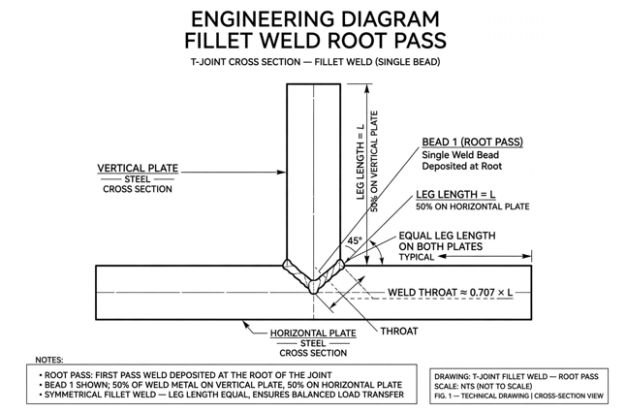
The pyramid model places one bead in the first layer, two in the second, and three in the third. This produces six beads in total. Larger welds may require more layers, but their sequence must remain consistent with the applicable WPS.
Root pass
Place the first bead at the joint root. Direct the arc so both members fuse without undercutting either toe. On an equal-leg fillet, the bead should distribute metal evenly across both plates.
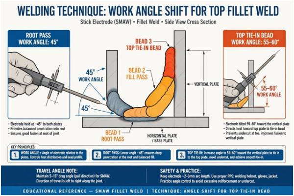
A centered electrode or gun angle is only a starting point. Joint position, process, electrode characteristics, and gravity may require adjustment. Watch both toes and the leading edge of the puddle rather than relying on angle alone.
Second layer
Place the lower bead first so it overlaps part of the root and creates support for the next pass. Then position the upper bead in the valley between the preceding deposit and the vertical member.
A 50% overlap is a useful practice reference, but it is not a mandatory value for every joint. The correct placement fills the valley without rolling one bead over another or leaving an unfused channel.
Upper layers and final tie-ins
Continue building from the lower side upward. Each new bead should sit partly on sound weld metal and partly against the area requiring fusion.
The uppermost pass deserves close attention. Poor electrode positioning can leave undercut on the vertical plate or slag at the toe. Pause only long enough to establish fusion; dwelling excessively can wash away the edge.
Multi-Pass Fillet-Weld Reference Table
| Layer | Typical beads | Placement target | Inspection checkpoint |
| First | 1 | Joint root | Root fusion and balanced legs |
| Second | 2 | Lower shelf, then upper valley | Smooth overlap without trapped slag |
| Third | 3 | Bottom-to-top pyramid fill | Fusion between every adjacent bead |
| Final | As specified | Complete required profile | Correct size, toes, contour, and finish |
This table is a planning reference. Weld size should come from the drawing or WPS rather than the number of visible beads.
Controlling Overlap, Travel Angle, and Bead Shape
Consistent stringers usually offer better control than one broad weave. A narrow bead makes the puddle easier to read and reduces the distance slag must travel before reaching the surface.
For the fillet weld multi pass stacking technique, aim the arc toward the leading edge and confirm fusion at both sides of each pass. Maintain a stable work angle while using travel speed to control bead width. Moving too fast creates a narrow, poorly tied-in bead. Moving too slowly can produce excess convexity, overlap, or undercut.
The bead edge from the previous pass should remain visible enough to guide the next deposit. If the surface forms a deep valley, remove or blend the irregularity before covering it.
The same puddle-reading discipline matters when learning the internal topic aluminum tig welding filler rod dab and pause method, although TIG aluminum requires different cleaning, filler, and shielding practices.
Interpass Cleaning and Temperature Control
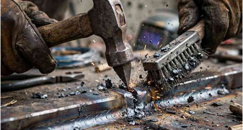
Remove slag after every SMAW or slag-producing FCAW pass. Use a chipping tool and wire brush, then inspect both toes and any valleys. Grinding may be necessary when a bead leaves sharp grooves, excessive convexity, or trapped material.
Do not assume the next arc will melt every contaminant away. Slag sealed between passes becomes an inclusion and can reduce the effective weld section.
Interpass temperature also matters. Heat accumulates rapidly during the fillet weld multi pass stacking technique, especially on short joints and thick deposits. Excess heat can enlarge the puddle, degrade bead control, and affect mechanical properties.
Follow the minimum and maximum temperatures stated in the WPS. Use an approved temperature-indicating crayon, contact thermometer, or infrared device suited to the procedure. TWI explains how preheat and interpass temperature influence welding performance and cracking control.
Worked Example: Planning a Six-Bead Fillet Weld
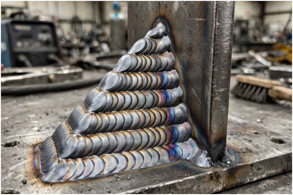
Consider a training T-joint that requires three layers. The first layer receives one root bead. The second receives a lower and upper bead. The third receives three beads placed from bottom to top.
That creates six beads, not three:
| Layer calculation | Beads | Running total |
| Layer 1 | 1 | 1 |
| Layer 2 | 2 | 3 |
| Layer 3 | 3 | 6 |
The useful insight is that bead count grows faster than layer count. Four complete pyramid layers would require 10 beads: 1 + 2 + 3 + 4. This affects deposition time, filler consumption, cleaning time, and accumulated heat.
Exact bead count can still vary. Electrode diameter, wire feed settings, joint size, position, and permitted weave width may change the layout.
Common Multi-Pass Welding Defects
| Defect | Likely stacking cause | Practical correction |
| Slag inclusion | Poor cleaning or a deep valley | Clean fully and blend sharp pockets |
| Lack of fusion | Arc directed onto existing weld metal | Aim at the unfused edge and slow slightly |
| Undercut | Excess heat, speed, or upper-toe dwell | Correct settings and stabilize travel |
| Overlap | Cold, oversized puddle rolling onto the plate | Reduce deposit size and improve arc placement |
| Excess convexity | Slow travel or oversized stringers | Increase travel speed within WPS limits |
| Unequal legs | Poor root alignment or work angle | Recenter the pass and watch both toes |
These checks also apply to vertical joints, although progression changes puddle behavior. The related internal guide vertical down stick welding 6010 root pass covers a specific electrode and progression method.
Procedure and Safety Requirements
Never select amperage, filler metal, preheat, or acceptance limits from appearance alone. Structural and code-regulated work requires the applicable drawing, qualified WPS, inspection criteria, and approved welder qualifications.
The American Welding Society publishes widely used US welding codes and standards. Lincoln Electric and Miller Electric provide process guidance and manufacturer documentation.
Arc welding also creates radiation, hot metal, sparks, fumes, and electrical hazards. OSHA’s welding, cutting, and brazing requirements address ventilation, fire prevention, screens, and worker protection. Use ventilation and task-appropriate PPE based on the actual process and material.
FAQs
1. How much should multi-pass fillet-weld beads overlap?
About one-half is a common visual starting point, but the WPS and required fusion determine the final placement.
2. Should I weave or use stringer beads for a large fillet weld?
Stringers usually provide better puddle and slag control unless the approved procedure permits a wider weave.
3. Do I need to clean every pass before stacking another bead?
Yes, remove slag and inspect the bead before depositing the next pass.
4. What is the correct order for the fillet weld multi pass stacking technique?
Establish the root, build the lower support bead, and fill successive valleys from the bottom upward.
Stack Smart, Not Just Big
A convincing weld profile cannot compensate for hidden slag or incomplete fusion. I treat the fillet weld multi pass stacking technique as a repeatable placement system: establish the root, clean thoroughly, fill each valley, monitor heat, and inspect before moving upward.
Practice the six-bead pyramid on scrap first. Cut and etch a sample when possible, because the cross-section reveals what surface appearance can hide.