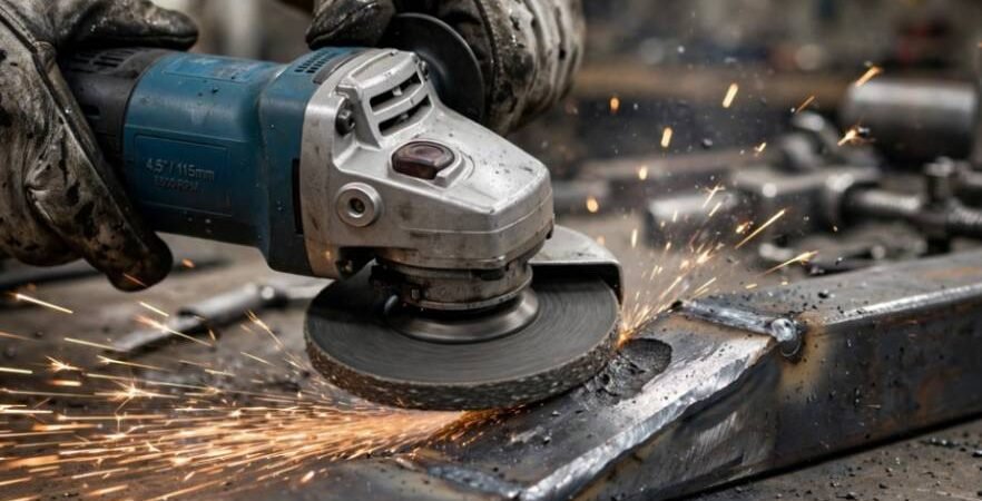
A poor joint tie-in breaks under X-ray, fails side-bend tests, and ruins joint integrity. Mastering the stick welding tie in technique stop and restart separates certified pipeline and structural hands from backyard hobbyists. Early in my structural career, my restarts looked like lumpy bird dropping clusters, and I spent hours grinding out slag traps.
A seamless restart requires three precise elements: mechanical crater preparation, controlled arc-strike placement, and thermal preheating. When done properly, the old bead and new bead merge into a continuous profile with uniform penetration.
Anatomy of a Weld Termination: Why Restarts Fail
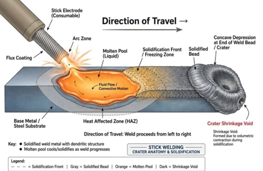
Every SMAW pass leaves a crater when you break the arc. As the molten pool freezes rapidly from the perimeter inward, shrinkage forces pull metal outward. This contraction leaves a depressed, concave cavity prone to shrinkage cracks and center-line pipes.
[Direction of Travel —>]
Solidified Bead Crater (Shrinkage Void)
====================\ /———————
\_____/ <— Slag & Porosity Hide Here!
\______________________
Unwelded Base Metal
Slag Traps and Lack of Fusion
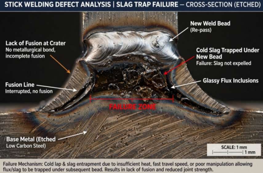
Slag melts at a different temperature than base steel. When you extinguish your rod, fluid slag washes directly into that low crater center. If you strike directly inside the frozen pocket, cold filler metal instantly freezes over trapped glassy flux, creating an irreversible failure zone.
According to structural welding codes published by the American Welding Society, internal slag inclusions and lack of root fusion account for a substantial percentage of non-destructive testing (NDT) failures. You cannot fuse steel through cold slag. You must expose pure, bare base metal before striking your replacement electrode.
Step-by-Step Stick Welding Tie In Technique Stop and Restart Execution
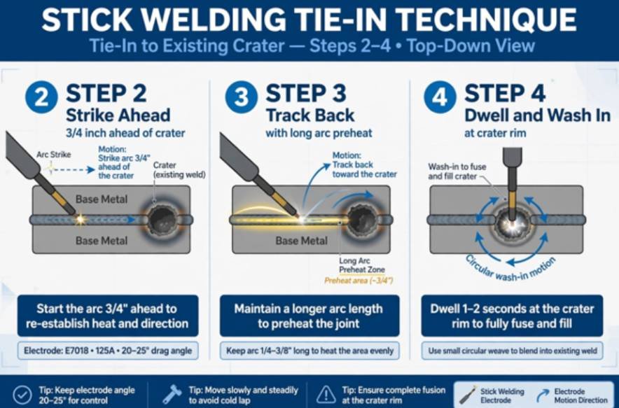
Executing a code-quality restart requires deliberate mechanical prep followed by an exact striking sequence.
Step 2: Strike Ahead Step 3: Track Back
(3/4″) (Long Arc Preheats)
* ————————-\
|
===================\ V
Solid Bead (Ground) \_______________[Crater Rim]
Step 4: Dwell & Wash In
The 20-Degree Feathering Rule
Never restart directly over a blunt, steep crater edge. I grab a 4.5-inch angle grinder with a 1/8-inch abrasive wheel or a carbide burr and grind the back half of the crater into a shallow slope.
I taper the frozen crown back roughly 3/4 inch at a 15-to-20-degree incline. The trailing ramp should terminate as thin as a knife blade against the joint base. This geometry eliminates high steps, allowing your fresh arc to wash liquid metal across the slope without bridging an air pocket underneath.
For heavy vertical structural columns, follow proper joint setups to stick weld vertical up 7018 without creating excessive crown buildup at each start.
Striking Ahead and Driving Back
- Clean completely. Chipping hammer first, then a stiff stainless-steel wire brush. Remove every trace of glass coat.
- Strike forward. Ignite your new electrode 1/2 inch to 3/4 inch ahead of the crater on the unwelded joint line. Never strike on the finished plate surface outside the weld zone; stray arc strikes cause localized martensite zones and micro-fissuring.
- Long-arc back. As soon as the rod fires, lift it slightly to draw a longer arc. Carry the electrode back across the joint path directly into the thinned knife-edge of the ground crater. The longer arc voltage preheats cold metal and prevents starting porosity.
- Dwell and tighten. Drop into a tight arc gap once you hit the back rim. Hold the rod stationary for a full count of two. Watch the solid crater rim melt and liquefy into your new puddle.
- Resume travel. Once the molten metal bridges the gap and reaches the previous bead profile, resume forward motion.
When you run open-root joints or dynamic passes, using a clean whip and pause stick welding technique helps regulate heat build-up on fast-freeze electrodes.
Technical Restart Parameters Across Electrode Classifications
Different electrode coatings govern how quickly the puddle freezes, how heavy the slag covers the crater, and where you strike. Technical papers from Lincoln Electric and Miller Electric confirm that rutile, basic, and cellulosic flux chemistries require distinctly different handling during restarts.
| Electrode Type | AWS Spec | Slag Volume & Viscosity | Strike Distance Ahead | Dwell Time at Crater Rim | Primary Defect Risk |
| Cellulosic | E6010, E6011 | Thin, fast-freezing, low volume | 1/2 inch | 1 second | Crater burn-through / suck-back |
| Low-Hydrogen | E7018, E8018 | Heavy, fluid, structural glass | 3/4 to 1 inch | 2 to 3 seconds | Cold lap, start porosity |
| Rutile | E6013, E7014 | Dense, fluid, low penetration | 1/2 inch | 1 to 2 seconds | Slag running ahead of pool |
| Iron Powder | E7024 | Extremely heavy, thick blanket | 1 inch | 2 seconds | Heavy internal slag inclusions |
Electrode-Specific Adjustments
- E7018 (Low Hydrogen): These rods are notorious for starting porosity caused by damp atmospheric exposure at arc ignition. Striking 3/4 inch ahead burns away internal contaminants before you reach the critical junction. Pre-cleaning requires immaculate mechanical grinding.
- E6010 (Cellulosic): These deliver a digging, violent arc. You do not need aggressive grinding; a brief chip and wire brush will suffice. Step into the keyhole crater immediately, drop your arc length, and push forward once the back wall melts.
- E6013 (Rutile): Slag fluidity is your primary enemy. Keep your arc tight as you return to the crater. If you pull a long arc, runny slag slips beneath your puddle, producing wormholes.
Visual Inspection and Quality Standards for Code Welds
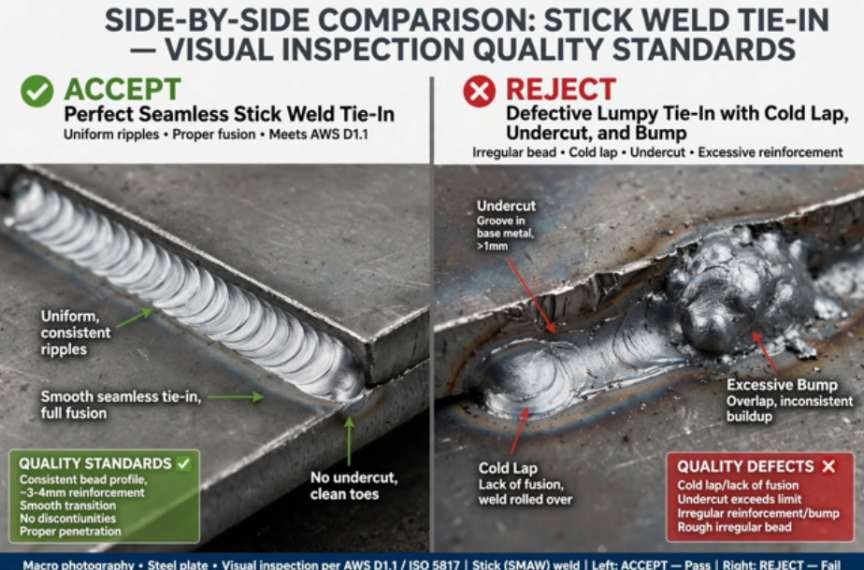
Inspect your tie-in visually before putting an angle grinder anywhere near the cover pass. According to industrial fabrication metrics from The Fabricator, a tie-in must match the adjacent bead dimensions within tight geometric tolerances.
| Inspection Checkpoint | Target Specification | Reject Criteria | Corrective Field Action |
| Bead Reinforcement | Flush to +1/16″ over base bead | Exceeds 1/8″ bump or saddle valley below joint plane | Blend crown flush using a 60-grit flap disk. |
| Toes of the Weld | Smooth transition (greater than 135° angle) | Sharp undercut deeper than 1/32″, cold lap rollover | Re-weld undercut; grind back cold lap boundaries. |
| Surface Finish | Uniform ripple spacing across splice | Visible pinholes, crater cracks, surface slag | Gouge or grind out the restart entirely and re-pass. |
Frequently Asked Questions
1. Why does my 7018 tie-in always show starting porosity?
You struck directly inside the crater instead of striking 3/4 inch ahead to burn out initial moisture before reversing into the pool.
2. Is mechanical grinding required on every stick welding restart?
Code and structural procedures mandate feathering craters with a grinder, though clean wire-brushing often suffices for non-critical cellulosic (E6010) passes.
3. How do I prevent a massive lump at my tie-in location?
Feather the old crater to a shallow 20-degree ramp and resume normal travel speed the second your puddle bridges the back rim.
4. What causes a tie-in to crack down the center?
Breaking your arc abruptly without filling the crater leaves a thin, concave shrinkage cavity that fractures under cooling stress.
Put Down the Grinder and Run it Seamless
A perfect tie-in should disappear completely under a wire wheel. Master the 20-degree feather, strike out ahead on the scrap groove, and give that back rim two seconds of clean heat before moving forward.
Put a couple of scrap plates in your vise today and practice ten restarts back-to-back until you can’t tell where the first rod ended and the next one caught fire.